Laser Guided Automated Calibrating System for Accurate Bracket Placement
2 Department of Orthodontics and Dentofacial Orthopedics, Yenepoya Dental College, Yenepoya University, Mangalore, Karnataka, India
Citation: Anitha A, Kumar AJ, Mascarenhas R, Husain A. Laser guided automated calibrating system for accurate bracket placement. Ann Med Health Sci Res 2015;5:42-4.
This open-access article is distributed under the terms of the Creative Commons Attribution Non-Commercial License (CC BY-NC) (http://creativecommons.org/licenses/by-nc/4.0/), which permits reuse, distribution and reproduction of the article, provided that the original work is properly cited and the reuse is restricted to noncommercial purposes. For commercial reuse, contact reprints@pulsus.com
Abstract
Background: The basic premise of preadjusted bracket system is accurate bracket positioning. It is widely recognized that accurate bracket placement is of critical importance in the efficient application of biomechanics and in realizing the full potential of a preadjusted edgewise appliance. Aim: The purpose of this study was to design a calibrating system to accurately detect a point on a plane as well as to determine the accuracy of the Laser Guided Automated Calibrating (LGAC) System. Materials and Methods: To the lowest order of approximation a plane having two parallel lines is used to verify the accuracy of the system. On prescribing the distance of a point from the line, images of the plane are analyzed from controlled angles, calibrated and the point is identified with a laser marker. Results: The image was captured and analyzed using MATLAB ver. 7 software (The MathWorks Inc.). Each pixel in the image corresponded to a distance of 1cm/413 (10 mm/413) = 0.0242 mm (L/P). This implies any variations in distance above 0.024 mm can be measured and acted upon, and sets the highest possible accuracy for this system. Conclusion: A new automated system is introduced having an accuracy of 0.024 mm for accurate bracket placement.
Keywords
Hough transforms, Indirect bonding technique, Laser, Orthodontic bracket placement
Introduction
It is widely recognized that accurate bracket placement is of critical importance in the efficient application of biomechanics and in realizing the full potential of a preadjusted edgewise appliance. When bands were used originally, Angle[1] thought the best position to place the bracket was at the center of the tooth. Later Ricketts[2] used marginal ridges as guidelines for the placement of bands and brackets. More recently, Andrews[3-6] introduced a bracket positioning technique of placing the vertical tie wings of the bracket parallel to the long axis of the clinical crown and then moving the bracket up or down until the middle of its slot base is at the same height as the midpoint of the clinical crown. Thurow[7] showed that two different vertical positions of a bracket on a tooth will cause two different buccolingual axial inclinations. Meyer and Nelson[8] showed that an error of 3 mm vertically in bracket placement on a premolar can result in 15° torque alteration and 0.04 mm alteration in/out adjustments. Variation in tooth morphology also plays an important role in bracket placement. Kraus[9] and Dellinger[10] found great variations existed in tooth structure that can affect treatment results.
In orthodontic literature, the advantages and disadvantages of direct and indirect bonding techniques have been discussed by many investigators.[11-16] In terms of accuracy of bracket placement, many reports indicated that Indirect bonding is superior because it is easier to place brackets on models than on teeth in vivo.[11,12,15,16] However, human errors have to be accounted for in these bonding techniques. Furthermore, the inadequacy of humans to resolve a point to a precision of 0.01 mm has made it difficult to place brackets accurately. In this study, we have proposed a computer aided, and laser guided technique in which a calibrated positioning device is used to overcome this problem.
Materials and Methods
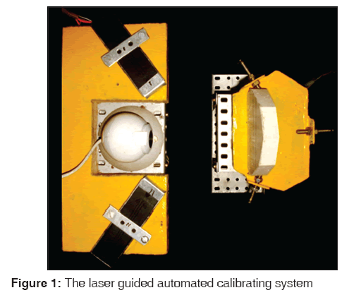
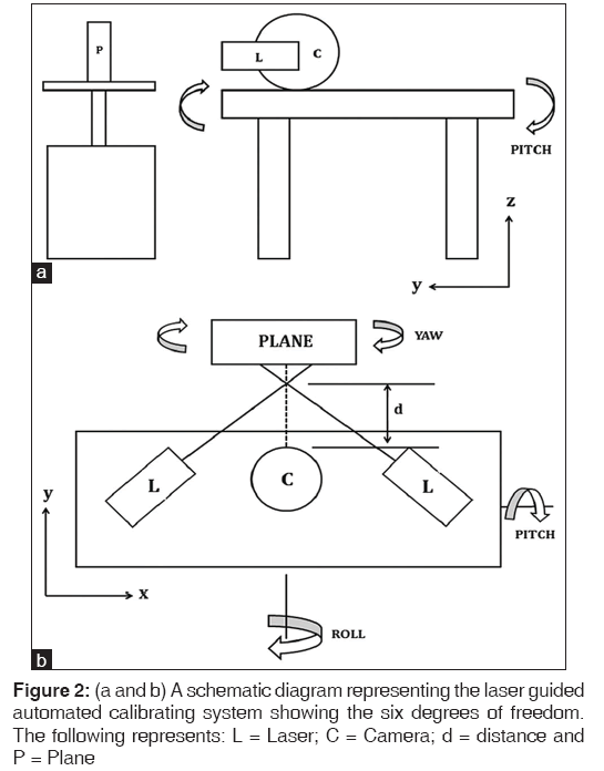
To the lowest order of approximation, a plane having two parallel lines is used as a test model to verify the accuracy of a laser-guided automated calibrating system. A charged coupled device (camera) with 640 × 480 resolutions is used to capture the laser spots. The captured images are processed using MATLAB ver. 7 software (The MathWorks Inc.). These images are in the form of matrices of size 640 × 480. 650 nm (red light) type III diode laser is used as a pointer with the beam radius of ~0.1 mm. Laser triangulation technique is used in such a manner that the lasers are placed on either sides of the camera and the two beams intersect at a fixed distance ‘d’ (~4 cm) in front of the camera [Figure 1]. Hence, if a plane is at a distance ‘d’ in front of the camera, we see only one laser spot. For any other distances, two spots will be visible.
Six stepper motors are used which are controlled one at a time through the PC parallel port with MATLAB ver. 7 software (The MathWorks Inc.). Each motor works with 5V DC supply and has a step size of 1.2°. The plane is mounted onto a stepper motor with its base perpendicular to the axis of rotation. This provides the yaw adjustments which help in locating the point to be processed. The laser and the camera setup is mounted onto the platform which has X-, Y-, Z-axis motion control and Pitch, Yaw, Roll degrees of freedom (DOF). The X- and Y-motion are achieved by converting rotary motion into linear by rack and pinion mechanism. The Z-motion, Roll and Pitch are achieved by mounting the platform on a tripod. The length of the tripod legs is changed through linear actuator mechanism in different combinations to produce the required motion [Figure 2a and b].
Determining the accuracy of the system
The plane has two parallel lines at a known distance ‘l’ between them. Automated alignment is carried out such that the lines in the image are horizontal, by adjusting the roll. Yaw and pitch alignment is also carried out. Now the plane with two parallel lines is exactly perpendicular to the plane formed by the laser beams. The lines on the plane are detected using Hough transform,[17] and the distance between them is determined in terms of number of pixels ‘P’. Hence, each pixel in the image would correspond to a distance of ‘l/P’. These calibration values are valid only at distance ‘d’ that is, when the laser spots coincide and the plane is perpendicular to the laser beams. Now if the height of the required point is specified, the Z-axis is adjusted such that the spots fall at the corresponding distance in pixels, from the top line of the plane. This is the required point.
Results
The laser beams converge at a distance of approximately 4 cm (d), which is decided by the lowest focal length of the camera unit. Calibration was carried out on the plane with two parallel lines separated by a distance of 10 mm (l). This was subjected to repeated calibration procedure as described earlier in order to eliminate any errors. The lines were detected, and the distance between the lines was estimated to be 413 pixels (P). Hence, each pixel in the image corresponds to a distance of 1 cm/413 (10 mm/413) = 0.0242 mm (l/P). This implies that any variations in distances above 0.024 mm can be measured and acted upon and sets the highest possible accuracy for this system.
Discussion
This device is designed to determine a point accurately on a plane using a laser guided automated calibrating system. This technology can be used to place the bracket accurately following few more trials. The initial set up was designed keeping this in mind. Here, instead of a study model we have used a plane having two parallel lines indicating the incisal and the gingival margin of the tooth. Once the image is captured, it is analyzed using MATLAB ver.7 software and the device is automatically calibrated until a single point is seen on the plane. In Orthodontics, this device can be used to improve the accuracy of bracket placement and thus improve treatment outcome.
Conclusion
Laser guided automated calibrating (LGAC) system can accurately locate a point on a plane as prescribed with the highest possible accuracy of 0.024 mm. It can also be used to calibrate any distance on a plane in relation to the six DOF, that is, Pitch, Roll, Yaw, X- Y- and Z-axis. Few more trials are necessary to be carried out with this prototype to achieve better efficiency in treatment by increasing the accuracy and decreasing chair-side time.
REFERENCES
- Angle HE. The latest and best in orthodontic mechanism. Dent Cosm 1928;70:1143-1158.
- Ricketts MR. Bioprogressive Therapy. 2nd ed. Rocky Mountain Orthodontics, Denver; 1979.
- Andrews LF. The straight-wire appliance, origin, controversy, commentary. J Clin Orthod 1976;10:99-114.
- Andrews LF. The straight-wire appliance arch form, wire bending and an experiment. J Clin Orthod 1976;10:581-8.
- Andrews LF. The straight-wire appliance. Explained and compared. J Clin Orthod 1976;10:174-95.
- Andrews FL. The S. W. A. Syllabus of Philosophy and Techniques. San Diego: LF Andrews Foundation for Orthodontic Education and Research; 1974.
- Thurow CR. Edgewise Orthodontics. 3 r d ed. St. Louis: CV Mosby; 1972.
- Meyer M, Nelson G. Preadjusted edgewise appliances: Theory and practice. Am J Orthod 1978;73:485-98.
- Kraus SB. Dental Anatomy and Occlusion. Ch. I. Baltimore: Williams and Wilkins; 1969.
- Dellinger EL. A scientific assessment of the straight-wire appliance. Am J Orthod 1978;73:290-9.
- Jarabak RL. Development of a treatment plan, in the light of one’s concept of treatment objectives. Am J Orthod 1969;36:481.
- Thomas RG. Indirect bonding: Simplicity in action. J Clin Orthod 1979;13:93-106.
- Hoffman BD. Indirect bonding with a diagnostic setup. J Clin Orthod 1988;22:509-11.
- MilneJW, AndreasenGF, Jakobsen JR. Bond strength comparison: A simplified indirect technique versus direct placement of brackets. Am J Orthod Dentofacial Orthop 1989;96:8-15.
- Proffit WR. Contemporary fixed appliances. In: Proffit WR, editor. Contemporary Orthodontics. St Louis: The CV Mosby Company; 1993. p. 342-73.
- Hickham JH. Predictable indirect bonding. J Clin Orthod 1993;27:215-7.
- Richard OH, Peter EH. Use of Hough Transformation to detect lines and curves in pictures. Commun ACM 1972;15:11-5.


 The Annals of Medical and Health Sciences Research is a monthly multidisciplinary medical journal.